
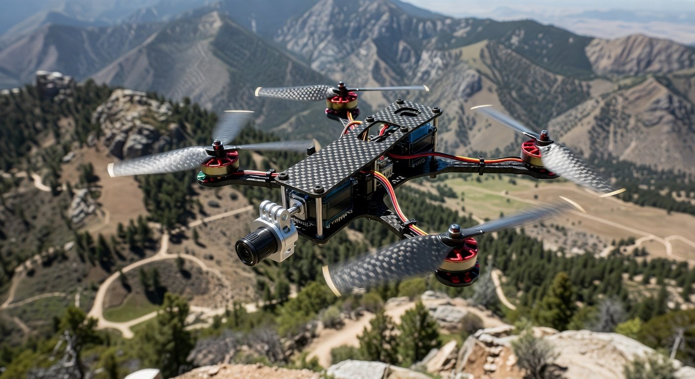
Understanding Automatic FPV Camera Tilt Systems
Automatic FPV camera tilt part 1 introduces pilots to the fundamentals of dynamic camera control systems that revolutionize flight footage capture. This technology automatically adjusts your FPV camera angle based on flight conditions, throttle input, or pre-programmed sequences, eliminating the need for manual gimbal control during high-intensity flying. The system typically consists of a servo motor, control board, and software integration that works seamlessly with your flight controller. Understanding these components forms the foundation for successful implementation and optimal performance in various flight scenarios.
The primary advantage of automatic camera tilt lies in its ability to maintain optimal viewing angles during aggressive maneuvers while keeping your hands free for flight control. Traditional fixed-angle cameras often result in ground or sky-heavy footage during climbs and dives, but automatic systems compensate by adjusting the camera angle in real-time. This technology particularly benefits freestyle pilots who perform complex acrobatic sequences and racing pilots who need consistent forward visibility through varying terrain. The system can be programmed with multiple modes, including throttle-based tilt, attitude-based adjustment, and manual override capabilities for maximum versatility.
Essential Components for Automatic FPV Camera Tilt Part 1
Building an automatic FPV camera tilt system requires specific hardware components that work together to provide smooth, reliable camera movement. The servo motor serves as the primary actuator, with micro servos being the most popular choice due to their compact size and sufficient torque for lightweight FPV cameras. Digital servos offer superior precision and response time compared to analog alternatives, making them ideal for rapid flight maneuvers. The servo must be capable of at least 180-degree rotation and should have metal gears for durability under vibration and impact stress.
The control system typically integrates with your existing flight controller through PWM signals or dedicated servo outputs. Popular flight controllers like Betaflight-compatible boards offer built-in servo control functionality, while standalone servo controllers provide additional features like programmable endpoints and speed control. Mounting hardware includes custom 3D-printed brackets or commercial servo mounts designed specifically for your frame and camera combination. Proper mounting ensures vibration isolation while maintaining rigid camera positioning throughout the tilt range. Additional components include servo extension cables, vibration dampeners, and protective covers to shield the servo from prop wash and debris.
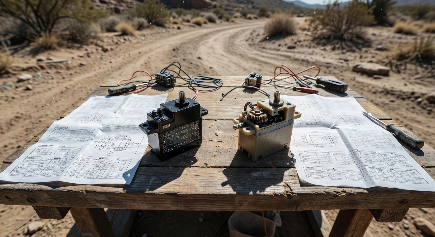
Servo Selection and Specifications
Choosing the correct servo for your automatic FPV camera tilt part 1 setup requires careful consideration of torque requirements, response speed, and physical dimensions. Micro servos with 1.5-3.0 kg-cm torque typically provide sufficient power for standard FPV cameras weighing 10-30 grams, including popular models like the Runcam Phoenix 2 or Foxeer Razer series. Digital servos offer faster response times, typically 0.08-0.12 seconds for 60-degree movement, compared to 0.15-0.20 seconds for analog servos. This improved response is crucial for maintaining smooth footage during rapid throttle changes or aggressive flight maneuvers that trigger automatic tilt adjustments.
Mechanical Installation and Mounting Techniques
Proper mechanical installation forms the foundation of a successful automatic FPV camera tilt part 1 system, requiring precise alignment and secure mounting to prevent mechanical failures during flight. The servo mount must position the servo output shaft in perfect alignment with the camera’s pivot point to avoid binding or excessive stress on the servo gears. Most installations utilize custom 3D-printed brackets that attach to the frame’s camera mounting points while providing servo mounting bosses and cable routing channels. The bracket design should incorporate vibration isolation features such as TPU dampeners or rubber grommets to minimize servo jitter from frame vibrations.
Camera mounting to the servo requires a lightweight yet rigid connection that maintains the camera’s center of gravity close to the pivot point. Aluminum or carbon fiber servo horns provide the necessary strength while minimizing rotational inertia that could cause servo oscillation. The camera should be balanced on the servo horn to reduce the holding torque required during flight, extending servo life and improving response characteristics. Proper cable management prevents wire fatigue and interference with moving parts, using spiral cable wrap or custom cable guides to maintain clean wire routing throughout the tilt range.
Frame Compatibility and Modifications
Integrating automatic camera tilt systems often requires frame modifications or careful selection of compatible frames that accommodate servo mounting without compromising structural integrity. Popular racing frames like the TBS Source One or freestyle frames such as the iFlight Nazgul series offer sufficient space for servo installation with minimal modifications. Frame modifications typically involve drilling mounting holes for servo brackets or removing material to provide servo clearance. When modifying carbon fiber frames, use sharp drill bits and low speeds to prevent delamination, and consider reinforcing mounting points with additional carbon fiber plates or aluminum standoffs.
Electrical Wiring and Connection Setup
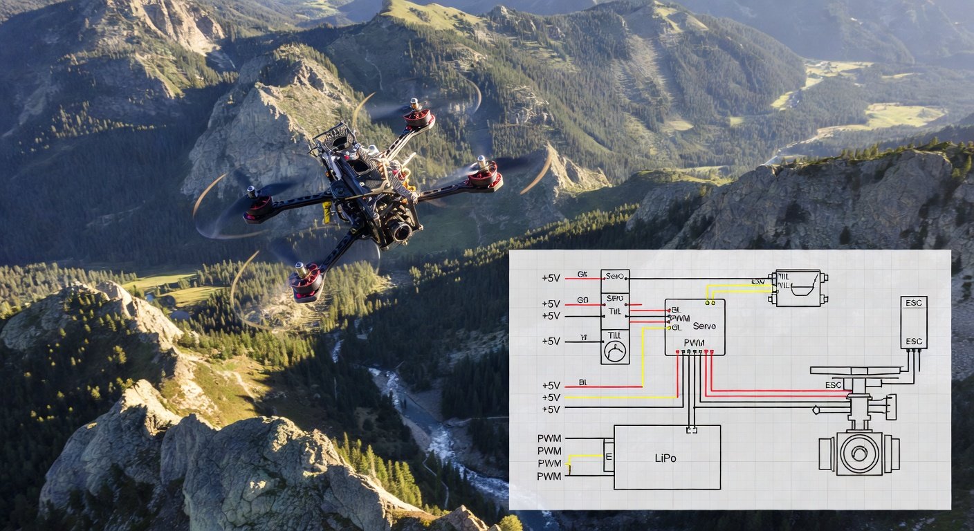
The electrical integration of automatic FPV camera tilt part 1 systems requires careful attention to power distribution, signal routing, and electromagnetic interference prevention. Servos typically operate on 5V power, which can be supplied directly from the flight controller’s 5V rail or through a dedicated BEC (Battery Elimination Circuit) for higher current requirements. Most micro servos draw 100-200mA during normal operation but can spike to 500-800mA during rapid movements or under load. Ensure your power supply can handle these current demands without voltage drops that could cause servo jitter or flight controller resets.
Signal wiring connects the servo control wire to a designated PWM output on your flight controller, typically AUX channels 1-4 depending on your configuration. Use high-quality servo extension cables with proper gauge wire to minimize voltage drop and signal degradation over longer runs. Twisted pair or shielded cables help reduce electromagnetic interference from ESCs and motors that could cause servo glitches. Proper grounding is essential, with the servo ground connected directly to the flight controller ground to establish a common reference point. Consider using ferrite beads on servo cables near high-EMI sources like ESCs or video transmitters to further reduce interference.
Power Management and Current Draw
Understanding power requirements is crucial for reliable automatic FPV camera tilt part 1 operation, as insufficient power can cause servo malfunction and potential flight controller issues. Digital servos typically require clean, stable 5V power with minimal ripple to operate correctly. Flight controller 5V rails often provide 1-2A capacity, which is usually sufficient for single servo applications. However, high-performance servos or multiple servo installations may require dedicated 5V BECs rated for 3-5A output. Monitor your system’s total 5V current draw including flight controller, receiver, and other peripherals to ensure adequate power margin for reliable operation throughout the flight.
Frequently Asked Questions
What servo specifications do I need for automatic FPV camera tilt part 1?
Choose a digital micro servo with 1.5-3.0 kg-cm torque, 0.08-0.12 second response time, and metal gears. Popular options include Savox SH-0257MG or Futaba S3010 servos that provide reliable performance for FPV camera weights.
Can I install automatic camera tilt on any FPV frame?
Most modern racing and freestyle frames can accommodate servo installation with proper mounting brackets. Some frames may require minor modifications like drilling mounting holes or clearance cuts for servo movement.
How much power does an automatic camera tilt system consume?
Typical micro servos draw 100-200mA during normal operation with spikes up to 500-800mA during rapid movements. Ensure your flight controller’s 5V rail can supply adequate current or use a dedicated BEC.
What flight controllers support automatic FPV camera tilt?
Most Betaflight-compatible flight controllers support servo control through PWM outputs. Popular options include Matek F722, Holybro Kakute, and HGLRC Zeus series controllers with dedicated servo outputs.
Ready to Build Your Automatic Camera Tilt System?
Transform your FPV footage with professional-grade automatic camera tilt technology. Our experienced team can help you select the right components and provide expert installation guidance for your specific setup. Contact us today to discuss your automatic FPV camera tilt part 1 project and take your aerial cinematography to new heights with dynamic camera control that adapts to your flying style.