
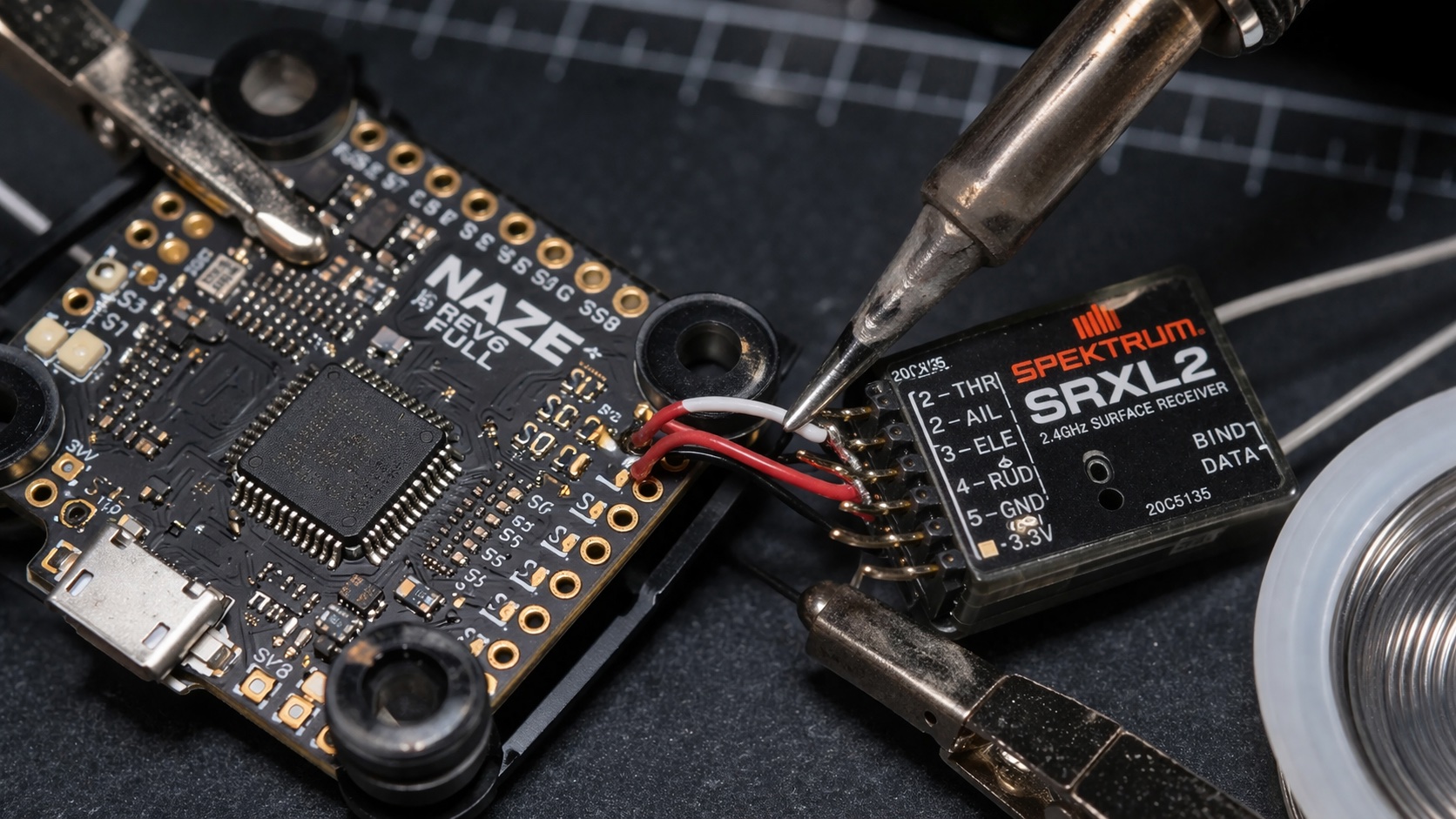
Understanding Spektrum Satellite Installation on Naze Rev6 FC Basics
The Spektrum satellite installation on Naze Rev6 FC represents one of the most reliable receiver configurations for racing and freestyle drones. The Naze Rev6 flight controller, manufactured by AbuseMark, features dedicated UART ports specifically designed for satellite receiver connections. This setup eliminates the need for traditional full-size receivers, reducing weight and improving crash resistance. The satellite receiver system uses DSM2 or DSMX protocols, providing excellent range and interference resistance. Understanding the fundamental connection principles between the Spektrum satellite and Naze Rev6 hardware forms the foundation for successful installation. The satellite receiver connects directly to the flight controller through a simple three-wire interface, carrying power, ground, and serial data signals.
Before beginning your spektrum satellite installation on naze rev6 fc project, gather the necessary components including the satellite receiver, appropriate gauge wire, and soldering equipment. The Naze Rev6 features multiple UART ports, with UART2 being the preferred connection point for satellite receivers. This configuration maintains compatibility with other peripherals while providing dedicated bandwidth for receiver communication. The satellite receiver operates on 3.3V logic levels, perfectly matching the Naze Rev6’s output specifications. Proper preparation includes reviewing the flight controller’s pinout diagram and identifying the correct solder pads. The installation process requires precision soldering skills and attention to detail to prevent damage to the sensitive electronic components.
Required Components and Tools for Spektrum Satellite Installation on Naze Rev6 FC
Successful spektrum satellite installation on naze rev6 fc requires specific components and professional-grade tools. The primary component is the Spektrum satellite receiver, available in various models including the SPM9645, SPM9646, or SPM9747. Each satellite model offers different features such as telemetry capability and protocol support. The Naze Rev6 flight controller must be genuine AbuseMark hardware to ensure proper UART functionality and voltage compatibility. Additional components include 30AWG silicone wire for flexible connections, heat shrink tubing for protection, and flux-core solder for reliable joints. Quality components prevent connection failures and signal interference that could compromise flight safety.
Essential tools for the installation include a temperature-controlled soldering iron set to 350°C, fine-tip soldering iron tips, flux paste, desoldering braid, and precision tweezers. A multimeter becomes crucial for continuity testing and voltage verification throughout the installation process. Magnification equipment such as a jeweler’s loupe or microscope helps identify the tiny solder pads on both the satellite receiver and flight controller. Proper lighting and a stable work surface prevent accidental damage during the delicate soldering process. Having backup components available protects against potential mistakes during the installation procedure.
Wiring Configuration and Connection Points
The spektrum satellite installation on naze rev6 fc follows a standardized three-wire configuration connecting power, ground, and signal lines. The satellite receiver’s positive power wire connects to the 3.3V output pad on the Naze Rev6, typically located near the processor or designated power distribution area. The ground connection links to any available ground pad on the flight controller, with multiple options available around the board perimeter. The signal wire connects to the RX2 pad, corresponding to UART2’s receive pin. This configuration allows the flight controller to receive serial data from the satellite while maintaining proper power delivery. Wire routing should avoid high-current paths and motor wires to prevent electromagnetic interference.
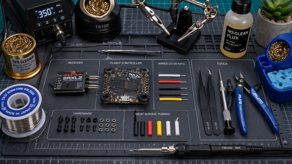
Essential components for spektrum satellite installation on naze rev6 fc project
Step-by-Step Spektrum Satellite Installation on Naze Rev6 FC Process
Begin the spektrum satellite installation on naze rev6 fc by preparing the satellite receiver for connection. Remove the existing connector from the satellite if present, exposing the three individual wires. Strip approximately 2mm of insulation from each wire end, being careful not to damage the fine copper strands. Apply flux to the exposed wire ends to improve solder flow and joint reliability. Pre-tin each wire with a small amount of solder to facilitate the connection process. Identify the wire colors: typically orange for positive power, black or brown for ground, and gray or white for signal. Verify these assignments against your specific satellite receiver documentation as color coding may vary between manufacturers.
Prepare the Naze Rev6 flight controller by cleaning the target solder pads with isopropyl alcohol and applying fresh flux. Heat your soldering iron to 350°C and tin the 3.3V, ground, and RX2 pads with thin solder layers. Position the satellite receiver in your desired mounting location, considering wire routing and potential interference sources. Solder the positive wire to the 3.3V pad first, followed by the ground connection to an appropriate ground pad. Complete the installation by connecting the signal wire to the RX2 pad, ensuring each joint is clean and mechanically secure. Allow all connections to cool completely before handling the assembly.
Mounting and Securing the Satellite Receiver
Proper mounting of the satellite receiver during spektrum satellite installation on naze rev6 fc significantly impacts signal reception and crash survivability. The satellite should be positioned away from carbon fiber components, as carbon fiber can interfere with 2.4GHz signals. Ideal mounting locations include the top plate of the frame or extended arms that provide clear signal paths. Use double-sided foam tape or hot glue to secure the satellite, avoiding rigid mounting methods that could transfer crash forces directly to the delicate receiver. The satellite’s antenna should extend beyond the frame structure when possible, maximizing signal reception in all orientations. Consider the satellite’s orientation relative to your typical flying positions to optimize signal strength.
Betaflight Configuration for Spektrum Satellite Installation on Naze Rev6 FC
Configuring Betaflight for your spektrum satellite installation on naze rev6 fc requires specific settings in the receiver configuration tab. Connect to your flight controller using the Betaflight Configurator and navigate to the Configuration tab. Set the receiver type to ‘Serial-based receiver (SPEKSAT, SBUS, SUMD, etc.)’ from the dropdown menu. Select ‘SPEKTRUM1024’ or ‘SPEKTRUM2048’ as the serial receiver provider, depending on your transmitter’s resolution settings. Most modern Spektrum transmitters use the 2048 resolution for improved precision. Configure UART2 as the serial receiver port in the Ports tab, enabling the serial RX function with a baud rate of 115200. These settings establish proper communication between the satellite receiver and flight controller firmware.
Additional configuration steps include setting up channel mapping and failsafe parameters specific to your Spektrum system. In the Receiver tab, verify that all channels respond correctly when moving transmitter sticks and switches. The channel order should follow the TAER format typical of Spektrum systems: Throttle, Aileron, Elevator, Rudder. Configure appropriate channel ranges, typically 1000-2000 microseconds for standard operation. Set failsafe values for each channel, with throttle set to minimum and other channels centered or in safe positions. Enable the ‘Channel Map’ feature if your transmitter uses non-standard channel assignments. Save all configuration changes and perform a thorough range test before first flight.
Troubleshooting Common Installation Issues
Common issues during spektrum satellite installation on naze rev6 fc include poor solder joints, incorrect wiring, and configuration errors. If the receiver tab shows no response from transmitter inputs, verify all solder connections using a multimeter for continuity. Check that the 3.3V power connection provides proper voltage using the multimeter’s DC voltage setting. Incorrect serial receiver settings in Betaflight can prevent communication, requiring verification of the receiver type and UART configuration. Signal interference from ESCs or video transmitters may cause intermittent control loss, necessitating satellite repositioning or additional shielding. Range issues often result from improper antenna orientation or carbon fiber interference, requiring physical relocation of the satellite receiver.
Testing and Validation of Your Spektrum Satellite Installation on Naze Rev6 FC
Comprehensive testing validates the success of your spektrum satellite installation on naze rev6 fc before attempting flight operations. Begin with bench testing using the Betaflight Configurator’s receiver tab, verifying smooth and responsive control inputs across all channels. Test the full range of motion for each control surface, confirming that stick movements translate to appropriate PWM values. Verify failsafe operation by powering off the transmitter and observing the failsafe response in Betaflight. The throttle should drop to minimum while other channels assume their programmed failsafe positions. Check for any glitches or dropouts during extended bench testing periods, as these may indicate connection or interference issues requiring resolution.
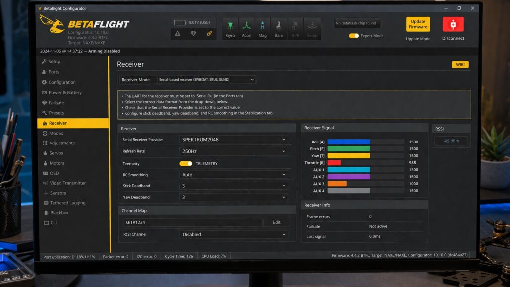
Betaflight settings for spektrum satellite installation on naze rev6 fc
Perform range testing in an open area away from potential interference sources, gradually increasing distance while monitoring control responsiveness. Standard Spektrum satellite systems should maintain solid control at distances exceeding 500 meters under ideal conditions. Test various orientations and positions to identify any dead spots or signal shadows that might affect flight operations. Validate telemetry functionality if your satellite supports this feature, confirming that flight data transmits correctly to your transmitter. Document your range test results and any observed anomalies for future reference. Only proceed to flight testing after confirming reliable operation during all bench and range tests.
Frequently Asked Questions
What voltage should I use for spektrum satellite installation on naze rev6 fc?
Use 3.3V from the Naze Rev6’s dedicated 3.3V pad. Never connect the satellite to 5V as this will damage the receiver. The Naze Rev6 provides clean, regulated 3.3V power specifically designed for satellite receivers.
Which UART port is best for spektrum satellite installation on naze rev6 fc?
UART2 is the preferred port for satellite installation on Naze Rev6. Connect the signal wire to the RX2 pad and configure UART2 as Serial RX in Betaflight’s Ports tab with 115200 baud rate.
Can I use any Spektrum satellite with the Naze Rev6 FC?
Most Spektrum satellites work with Naze Rev6, including SPM9645, SPM9646, and SPM9747 models. Ensure your satellite supports DSM2 or DSMX protocols and operates on 3.3V logic levels for compatibility.
How do I troubleshoot no signal issues after spektrum satellite installation on naze rev6 fc?
Check solder connections with a multimeter, verify 3.3V power supply, confirm correct Betaflight receiver settings (SPEKTRUM1024/2048), and ensure UART2 is enabled as Serial RX. Reposition satellite away from carbon fiber if signal remains weak.
Need Professional Help with Your Spektrum Installation?
Complex installations like spektrum satellite installation on naze rev6 fc require precision and experience. Our certified technicians provide professional installation services, ensuring your setup performs flawlessly from day one. Contact us for expert assistance with your flight controller configuration and receiver installation needs.